Design Archives | IN3DTEC | Prototyping & On-demand manufacturing services https://www.in3dtec.com/category/design/ 3D Printing | CNC Machining | Vacuum Casting | Injection Moding, Competitive price with a quick turnaround. Wed, 14 May 2025 02:08:30 +0000 en-US hourly 1 https://wordpress.org/?v=6.8.1 https://www.in3dtec.com/wp-content/uploads/2023/08/cropped-IN3DTEC-LOGO-32x32.png Design Archives | IN3DTEC | Prototyping & On-demand manufacturing services https://www.in3dtec.com/category/design/ 32 32 How to Save 3D Printing Costs Through Smart Design Choices https://www.in3dtec.com/how-to-save-3d-printing-costs-through-smart-design-choices/ Tue, 04 Jun 2024 01:37:20 +0000 https://www.in3dtec.com/?p=18263 How to Save 3D Printing Costs Through Smart Design Choices 3D printing has revolutionized manufacturing, allowing creators to turn digital designs into physical objects with ease. However, the cost of 3D printing can add up quickly, especially for complex or high-volume projects. Fortunately, strategic design choices can significantly reduce these costs. Here are some tips from […]

The post How to Save 3D Printing Costs Through Smart Design Choices appeared first on IN3DTEC | Prototyping & On-demand manufacturing services.

]]>

How to Save 3D Printing Costs Through Smart Design Choices

3D printing has revolutionized manufacturing, allowing creators to turn digital designs into physical objects with ease. However, the cost of 3D printing can add up quickly, especially for complex or high-volume projects. Fortunately, strategic design choices can significantly reduce these costs. Here are some tips from our printing team on how to save on 3D printing expenses by optimizing your designs.

1. Optimize Your Design for Material Usage

. Hollow Out Your Models

– Why: Reducing the amount of material used can drastically cut costs.

– How: Use software tools to hollow out solid parts, leaving enough wall thickness to maintain structural integrity.

– Recommended wall thickness: SLA resins for 2.5mm minimum, SLS nylons between 2mm to 5mm, SLM metals for 1.2mm minimum, FDM Plastics 1.2mm minimum.

. Use Infill Wisely-Ideal for FDM 3D Printing only

– Why: The density of the infill impacts both material use and print time.

– How: Choose a lower infill density for non-structural parts. A 20-30% infill is often sufficient for most applications, striking a balance between strength and material savings.

2. Minimize Supports and Overhangs

. Design with Self-Supporting Angles

– Why: Supports add to material costs and require additional post-processing.

– How: Design parts with overhang angles greater than 45 degrees to minimize the need for supports. Integrate features like chamfers or fillets to support overhangs.

. Split Complex Models

– Why: Large, intricate parts may require a lot of supports.

– How: Break down complex models into simpler parts that can be printed without supports and then assembled post-printing.

3. Choose the Right Material

. Consider Cost-Effective Filaments

– Why: Different materials vary greatly in cost.

– How: For prototyping and non-functional parts, opt for cheaper materials like PLA instead of more expensive options like ABS or PETG. Get instant 3D Printing quote in different materials from this link.

. Leverage Material Properties

– Why: Some materials offer better properties that might reduce the need for additional design features.

– How:Use flexible materials for parts that require bending, or durable materials for high-stress components to avoid over-engineering your design.

 4. Optimize Print Settings

. Layer Height Adjustments

– Why: Thicker layers mean fewer layers to print, saving time and material.

– How: Increase the layer height for parts where fine detail is not critical. For example, use a 0.2mm layer height instead of 0.1mm.

-Example: In MJF printing, there are two different options, the fast mode and balanced printing mode. The last one results in high quality parts with much better smoothness. In FDM printing, the biggest nozzle diameter is 1.0mm, which means that it can print same parts with shortest time.

. Print Speed and Temperature

-Why: Optimized print speeds and temperatures can reduce time and material waste.

– How: Calibrate your printer settings to ensure efficient material use without compromising print quality.

5. Design for Assembly

. Modular Design

– Why:Smaller parts can be printed faster and with less material.

– How: Design your model in modular components that can be easily assembled post-printing.

. Use Fasteners and Snap Fits

– Why: Reducing the need for large, solid components cuts down on material usage.

– How:Incorporate features like snap fits or design your parts to be joined using fasteners rather than printing large, monolithic pieces.

 6. Leverage Advanced Software Tools

. Utilize Slicing Software Features

– Why: Modern slicing software offers numerous settings to optimize prints.

– How: Explore options such as variable layer height, adaptive infill, and support structure optimization to reduce material use and print time. Tree support is recommended for most of the parts.

-Recommended software: Let’s say FDM 3D Printing, using software such as Prusa Slicer, Cura, Simplify3d, Bambu studio, OrcaSlicer

. Use Simulation and Analysis Tools

– Why: Understanding how your design performs under stress can prevent over-designing.

– How: Use simulation tools to analyze the load-bearing capacity of your design and adjust accordingly to use less material without sacrificing strength.

Conclusion

By making informed design choices, you can significantly reduce the cost of 3D printing. Focus on material efficiency, minimize the need for supports, choose the right materials, optimize your print settings, design for assembly, and leverage advanced software tools. These strategies not only help in saving costs but also contribute to faster production times and better overall print quality. Happy printing!

Feel free to reach out [email protected]if you have any questions or need further assistance with your 3D printing projects.


The post How to Save 3D Printing Costs Through Smart Design Choices appeared first on IN3DTEC | Prototyping & On-demand manufacturing services.

]]>
Exploring Different Types of Springs and Their Applications https://www.in3dtec.com/exploring-different-types-of-springs-and-their-applications/ Thu, 16 Nov 2023 07:53:41 +0000 https://www.in3dtec.com/?p=17290 Exploring Different Types of Springs and Their Applications Introduction: Springs are versatile mechanical devices that store and release mechanical energy, making them essential components in various industries and applications. From simple coil springs to complex torsion springs, each type serves a specific purpose. In this blog, we will delve into the different types of springs […]

The post Exploring Different Types of Springs and Their Applications appeared first on IN3DTEC | Prototyping & On-demand manufacturing services.

]]>

Exploring Different Types of Springs and Their Applications

Introduction:

Springs are versatile mechanical devices that store and release mechanical energy, making them essential components in various industries and applications. From simple coil springs to complex torsion springs, each type serves a specific purpose. In this blog, we will delve into the different types of springs and explore their wide-ranging applications.
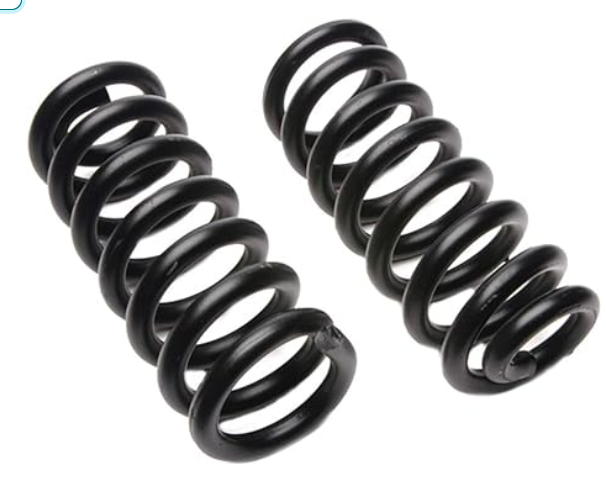
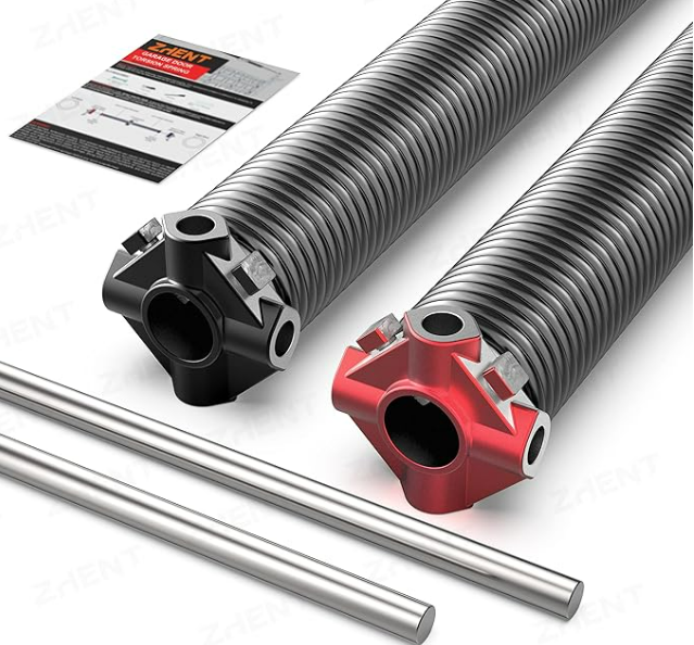
1.Coil Springs:

Coil springs are the most common type of springs, consisting of a helical coil shape. They can be further classified into compression springs, extension springs, and torsion springs. Compression springs absorb and store energy when compressed and are widely used in automotive suspension systems, industrial machinery, and consumer products. Extension springs, on the other hand, expand and store energy when pulled, making them suitable for garage doors, trampolines, and various mechanical systems. Torsion springs apply torque and are commonly found in clothespins, vehicle suspension systems, and even mousetraps.
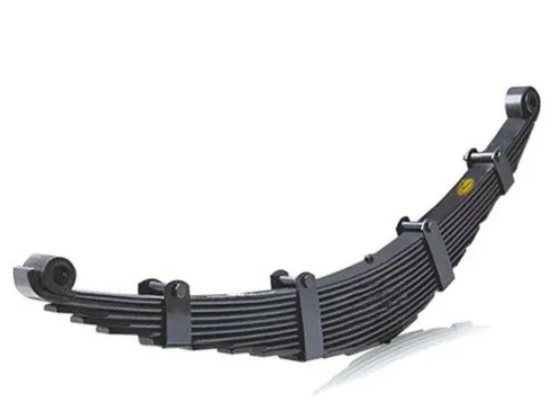
2.Leaf Springs:

Leaf springs are made up of multiple layers of curved metal strips, or leaves, bound together. They provide suspension support and are commonly used in vehicles such as trucks, trailers, and some passenger cars. Leaf springs offer excellent load-carrying capacity and stability, making them ideal for heavy-duty applications.

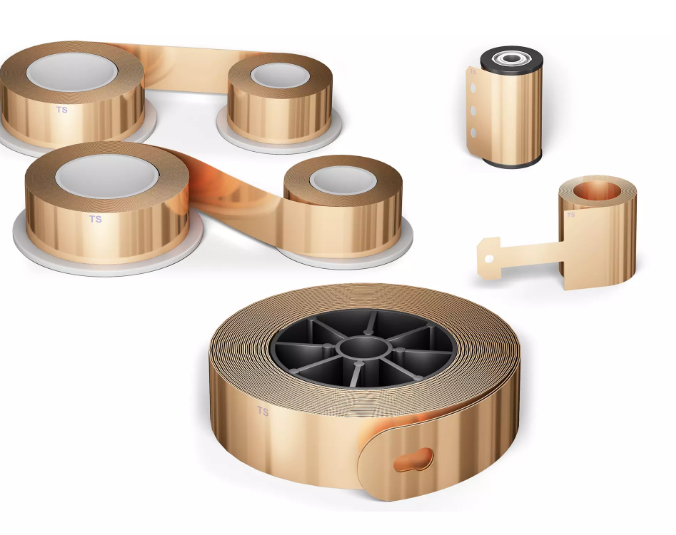
3.Constant Force Springs:

Constant force springs are a unique type of spring that provides a constant force throughout their range of motion. They are often used in applications that require a smooth and consistent force, such as retractable tape measures, window blinds, and counterbalance mechanisms.

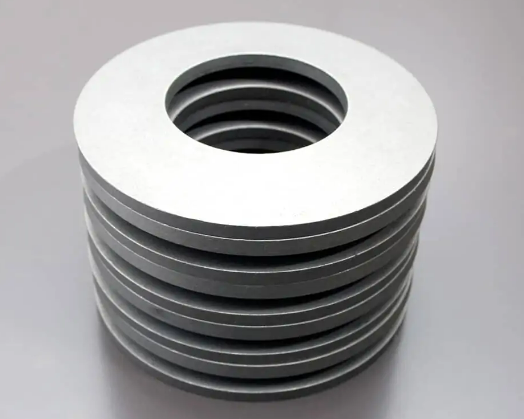
4.Belleville Springs:

Belleville springs, also known as disc springs or conical springs, are conically shaped and provide high spring loads in confined spaces. They are widely utilized in pressure relief valves, bolted connections, and disk brakes, where their ability to handle high loads and maintain consistent pressure is crucial.
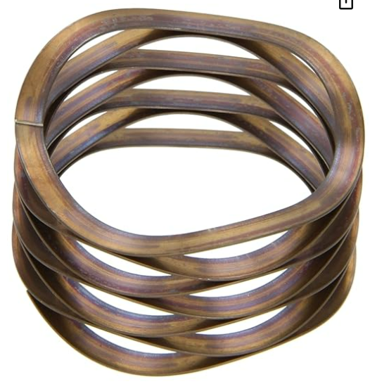
5.Wave Springs:

Wave springs are flat or coiled springs that are designed with a wave-like shape. They offer a compact and lightweight solution for applications with limited space. Wave springs are commonly used in aerospace, medical devices, and precision equipment, where their low spring rates and precise load requirements are advantageous.
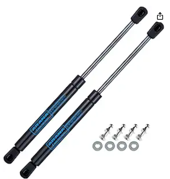
6.Gas Springs:

Gas springs, also known as gas struts or gas lifts, are filled with compressed gas and are used for controlled lifting, lowering, and damping motions. They are commonly found in office chairs, automotive hatches, hospital beds, and industrial machinery, providing smooth and controlled movement.
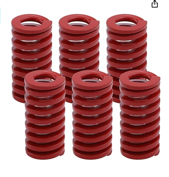
7.Die Springs:

Die springs are heavy-duty compression springs specifically designed for high-stress applications, such as stamping and metal-forming dies. They are known for their durability, reliability, and ability to withstand repetitive loads, making them critical in industrial manufacturing processes.
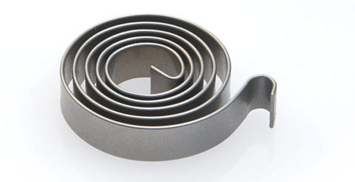
8.Clock Springs:

Clock springs, also known as power springs, are spiral-shaped springs used in applications that require rotational energy storage and release. They are commonly found in mechanical clocks, watches, and spring-driven devices. Clock springs provide the necessary force to wind up the mechanism and release it gradually to power the timekeeping mechanism.
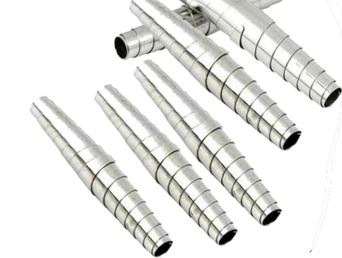
9.Volute Springs:

Volute springs are unique spiral springs with a conical shape and varying pitch. They are used in applications that require high force and limited space, such as in electrical switches, safety valves, and clutch mechanisms. Volute springs provide a high amount of force in a compact design, making them suitable for applications where space is a constraint.

10. Torsion Bar Springs:

Torsion bar springs, also known as torsion bars, are long, straight bars designed to resist twisting forces. They are commonly used in vehicle suspension systems to provide stability and control. Torsion bar springs absorb and distribute the forces generated during vehicle movement, helping to maintain a smooth ride.

Conclusion:

Springs play a vital role in numerous industries and applications, providing mechanical support, control, and energy storage. Understanding the different types of springs and their applications is essential for engineers, designers, and anyone working with mechanical systems. Whether it’s the compression springs in your car’s suspension, the leaf springs supporting heavy loads, or the gas springs providing smooth motion, each type of spring serves a specific purpose, contributing to the efficiency and functionality of countless products and systems.

The post Exploring Different Types of Springs and Their Applications appeared first on IN3DTEC | Prototyping & On-demand manufacturing services.

]]>
Design guide for injection molding https://www.in3dtec.com/design-guide-for-injection-molding/ Sun, 22 May 2022 04:57:19 +0000 https://www.in3dtec.com/?p=11844 Design guide for injection molding Injection molding is a formative manufacturing technology, i.e. material is formed from an amorphous shape into a fixed shape defined by a mold tool. Almost every plastic part created today is by injection molding as it allows identical parts to be created in huge numbers, in a short space of […]

The post Design guide for injection molding appeared first on IN3DTEC | Prototyping & On-demand manufacturing services.

]]>

Design guide for injection molding

Injection molding is a formative manufacturing technology, i.e. material is formed from an amorphous shape into a fixed shape defined by a mold tool. Almost every plastic part created today is by injection molding as it allows identical parts to be created in huge numbers, in a short space of time, and at very low cost per part.

Best practice design guides aim to help create complex shapes while:
• Allowing plastic to flow easily and uniformly around the part.
• Allowing the plastic to cool quickly and evenly, resulting in a stable and accurate part.

These general tips will improve part quality, mold ability and cycle time based on known implementation and characteristics of the injection molding process.

Draft angle

Draft, or the application of a slight taper to every surface in the direction of pull on an injection-molded part, is a small and even tedious design element — but one that’s vital to the success of a project. To visualize draft, envision an ice cube tray: the slight taper allows ice cubes to slide out easily without falling victim to excessive suction or friction. Parts that are lacking the appropriate amount of draft — or a suitable draft substitute — will not properly eject from the mold.

What’s more, draft protects the part from damaging friction, reduces wear and tear during the ejection process, helps ensure a uniform finish, and reduces costs by avoiding the need for complex injection setups. Fortunately, no toolmaker would make a part without draft. For that reason, designing for optimized draft angles doesn’t just mean adding draft; in most cases, draft is a given. Rather, optimizing draft means carefully incorporating draft so that it adds to, rather than interferes with, the design and look of the final part.

The minimum draft angle for any given part is largely driven by the depth of draw, the wall thickness, the material’s shrink rate, and the surface finish or texture that is to be applied. As a general rule, a draft angle of 1.5 to 2 degrees is required for most parts, but draft should average about an additional degree for each extra inch of part depth. Note that if a part is very small, there’s some more flexibility to decrease draft below 1.5 degrees. However, for most parts, 1.5 degrees is the minimum draft requirement.

That said, texture also plays an important role in determining draft. Many injection-molded parts have a leather grain or other texture applied to their surface for aesthetic purposes; however, depending on how deep the texture is, the draft angle may need to be increased to ensure the texture won’t be scraped off or damaged during the ejection process.

Automobile interiors are a strong example of strategically-applied draft. Most modern automobile interiors are injection-molded but feature a leather grain texture; a careful eye can discern that the texture depth varies throughout the part in order to accommodate changing draft, but it’s barely noticeable. On the other hand, many cheaply-made consumer goods have visibly different textures throughout the part or even texture that has been noticeably scraped off.
 
Wall thickness

If you take apart any of the plastic appliances around your home (as most engineers probably did as children) you’ll notice that the walls for most parts are about 1 mm to 4 mm thick (the optimal thickness for molding), and uniform for the entire piece. Why? Two reasons.
 
First of all, thinner walls cool faster, shortening the cycle time of the mold, the amount of time it takes to make each part. If a plastic part can cool faster after the mold is filled, then it can safely be ejected sooner without warping, and because time on the injection machine costs money, the part is less expensive to produce.
 
The second reason is uniformity: In the cooling cycle, the outer surface of a plastic part cools first. Cooling causes contraction; if the part is of uniform thickness, then the entire part will shrink away from the mold uniformly as it cools, and the part comes out smoothly.
 
However, if the part has thick and thin sections next to each other, then the molten center of the thicker area will continue to cool and contract after the thin areas and surfaces have already solidified. As this thick area continues cooling, it keeps contracting, and it can only pull material from the surface. The result is a little dimple on the surface of the part called a sink mark.

Happily, thick walls have some simple solutions. The first thing to do is to notice the areas which are a problem. In the part below, you can see two common issues: thickness around screw holes, and thickness where strength is needed in the part.
 
For screw holes in an injection molded part, the solution is to use “screw bosses”: a small cylinder of material directly around the screw hole, tied to the rest of the housing using a rib or a flange of material. This allows for more uniform wall thickness and fewer sink marks.

When an area of the part needs to be especially strong, but the wall is too thick, the solution is similarly simple: ribbing. Instead of making the entire part thick and difficult to cool, thin the exterior face into a shell, then add vertical ribs of material to the interior for strength and rigidity. In addition to easier molding, this reduces the amount of required material, reducing costs.

Radii

Correct placement of corner radii in injection moulding design creates strong, high-quality and cost-effective plastic parts. Sharp external corners are ok and sometimes necessary to fulfill product requirements, such as triangular shaped items. However sharp corners can present challenges when designing for injection moulding, as they can cause stress resulting in a poor product, radii are key to reducing stress.
 
There are two types of radius, internal and external. Internal edges should be rounded to a minimum of 0.5 times the wall thickness. External edges should be rounded to a minimum of 1.5 times the wall thickness.

Thread Features

There are two main ways to add a thread into an injection molded part. Each method has its merits and is suited to different applications.

Molded Thread

A molded thread is a thread molded directly into the tool (an example of this is a bottle lid). Because the thread creates undercuts, then in order to remove the part from the tool, the thread will need to be unscrewed. For this reason, the tool will need to be more complex and costly.
Generally, this will be best suited to larger threads on a simpler overall part.

Bosses

Bosses are very common method of creating an attachment point in injection molding. They are simply cylindrical extrusions that can accommodate a self-tapping screw, metal threaded insert or feature from another part.

Metal threaded inserts can be added into the boss by ultrasonic, thermal or in-mold insertion. These allow machine threads and are well suited to higher load applications or which require many cycles of assembly and disassembly.

Best design practice for bosses are as follows:
-Outside diameter 2 times the internal diameter.
-Add chamfer to guide screw or insert into hole.
-The hole should extend to the wall level.

Undercuts
 
Achieving success with undercuts requires minor mold modifications and a lot of expertise. Some of the designs that can help avoid defects and wearing of the mold include:

Parting Lines: By moving the parting line and adjusting draft angles to intersect an undercut, you can prevent part defects. The parting line placement is limited according to the geometry, material flow, and other features of the part.

Side-Actions: A perpendicular side-action is ideal for cylindrical parts, as the mold is split horizontally along the part. After the resin is shot into the mold and begins to cool, the side-action slides on an angled pin until its clear from the undercut, allowing it to be freely ejected.

Sliding Shutoffs: This technique uses create clip- and hook-style components to lock together two halves of a mold. During mold operation, these mechanisms seal together, “shutting off” certain areas of the part to create complex features, such as holes.

Bump Offs: If you have a mild undercut, you can make a separate insert that bolts into the mold. Upon ejection, the plastic briefly stretches over the insert but subsequently resumes its desired form.

Hand-loaded Inserts: A machined insert is hand-loaded into the mold to prevent molten plastic from flowing into these areas. Upon completion of the cycle, the inserts are ejected with the part, where an operator is required to pick them off the part for further use.

The post Design guide for injection molding appeared first on IN3DTEC | Prototyping & On-demand manufacturing services.

]]>
Mechanical Properties Every Design Engineer Should Know https://www.in3dtec.com/mechanical-properties-every-design-engineer-should-know/ Sat, 21 May 2022 08:30:46 +0000 https://www.in3dtec.com/?p=11700 Mechanical Properties Every Design Engineer Should Know Mechanical properties are those that determine the behavior of a material under the forces applied to it and reflect the relationship between its response to a load and the deformation it undergoes. In other words, the mechanical properties of materials help us to measure how materials behave under load in order […]

The post Mechanical Properties Every Design Engineer Should Know appeared first on IN3DTEC | Prototyping & On-demand manufacturing services.

]]>

Mechanical Properties Every Design Engineer Should Know

Mechanical properties are those that determine the behavior of a material under the forces applied to it and reflect the relationship between its response to a load and the deformation it undergoes. In other words, the mechanical properties of materials help us to measure how materials behave under load in order to achieve optimum system performance. 
 
Material Stress and Strain
First, we need to explain some of the physical concepts behind the mechanical properties. The main one is stress. Stress tells you how big of a force applies to an area. In mechanical engineering, it is mostly expressed in MPa’s or N/mm2. Those two are interchangeable.

The formula for stress is:
σ=F/A, where F is force (N) and A is area (mm2).

The second important concept is strain. Strain has no unit as it is a ratio of lengths. It is calculated as follows:
ε=(l-l0)/l0, where l0 is starting or initial length (mm) and l is stretched length (mm).
 
Young’s Modulus
From those two concepts we get to our first mechanical properties – stiffness and elasticity as its opposite. It is an important factor for engineers when solving physics problems (material suitability for a certain application).

Stiffness is expressed as Young’s modulus, also known as modulus of elasticity. As one of the primary mechanical properties of materials, it defines the relationship between stress and strain – the bigger its value, the stiffer the material.

This means that the same load would deform two equally-sized parts differently, if they have varying Young’s moduli. At the same time, lesser value means that the material is more elastic.

Yield Strength
Yield stress or yield strength is the value most often used in engineering calculations. It gives a material a stress value in MPa it can take before plastic deformation. This place is called the yield point. Before it, a material regains its former shape when lifting the load. After exceeding the yield point, the deformation is permanent.

There is a good reason for using yield stress as the most important factor in mechanical engineering. As can be seen from the stress-strain curve, when stress goes beyond the yield point, the damage is not yet catastrophic. That leaves a “cushion” before a construction fails completely to the point of breaking.

Tensile Strength
Ultimate tensile strength, or just tensile strength, is the next step from yield strength. Also measured in MPa’s, this value indicates the maximum stress a material can withstand before fracturing.

When choosing a suitable material to tolerate known forces, two materials with a similar yield strength may have different tensile strengths. Having higher tensile strength may help to avoid accidents, if unforeseen forces are applied.

Hardness
Hardness refers to the ability of a material to withstand scratching or indenting on its surface. It is one of the most commonly used material properties and can be applied to any solid material. Obviously, harder materials are more difficult to scratch or dent.

There are several standard hardness scales and testing methods that can be used. The most common scales are the Rockwell, Vickers and Brinell hardness scales. 

A piece of material might be called out as 45 Rc (Rockwell C scale). The hardness is measured using a calibrated machine that measures the force required to put a small indentation in a material sample.

While certain materials will naturally be harder than others (steel will always be harder than aluminium, for example), the hardness of many materials can be increased or decreased by heat-treating or work hardening.

Hardness is extremely useful for a design engineer. For example, an engineer will generally specify a minimum hardness for something like a hammer to ensure that it does not easily scratch or dent when used under normal conditions. However, it may be a good idea to anneal a stainless steel part that will be machined in a later process to make sure it isn’t too hard for the cutting tools that will be used.

The post Mechanical Properties Every Design Engineer Should Know appeared first on IN3DTEC | Prototyping & On-demand manufacturing services.

]]>